
|
|
SMS Moltke: The making of Mein Boot
Here I put down the details to the thinking and planning process that I went through trying to get my ship to the water. However, there is a big difference between the original concept I had for my ship and the way it actually came out. I have happened to come into the hobby about the same time that a number of interesting changes were taking place. The tried and true method of controlling a boat's speed and armament was by using mechanical switches and valves activated by servos. However, a recent innovation has been to use ESCs (Electronic Speed Control) and circuit boards/solenoids to perform these functions. These systems have the advantage of cutting out a lot of mechanical linkages that could be temperamental (especially for craftsman like me with two left thumbs!). They interface directly with the radio receiver, which eliminates the need for servos (in fact, my boat has only one servo, to control the rudder). Also, the individual components for this system either come waterproofed, or can be waterproofed with a product called ScotchKote. Consequently, the need for a waterproof radio box is eliminated, and the electronics can be stuck into nooks and crannies of the boat. The disadvantage is that these components tend to cost a bit more than a similar set up with servos, but that was a trade-off I was willing to make.
First, A Word on Graphics
Here is a link to the plan that I found published on Mr. Tanner's website. It has an awful lot of detail in it, even a bit more than the plans that I am using to actually build the ship! I apologize for the poor quality of the thumbnails, but the graphics themselves are fine and aren't that large anyway.
Based on those planes, I prepared these simplified drawings to illustrate the layout of my boat.
![]()
![]()
Internal Arrangement
This image shows roughly how I intended to lay out the internal components of my ship. This layout was fairly conventional, at least in the Maryland area. The battery was the single heaviest component, so it has to be laid flat in order to preserve the boat's stability. I was planning to use an Otter Box to protect my radio, which would have eliminated the need to build a box from scratch. The width of this box dictated that it be placed as close to amidships (where the hull is wide enough to accommodate it) as possible. The pump was to be placed as far aft as possible, since water will have a tendency to collect there when the ship is moving forward.

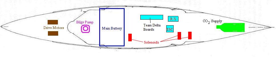
Internal Arrangement Revised
Here is how things really turned out. Obviously, there are some similarities to the old arrangement. The battery, pump, and CO2 supply are all in roughly the same place, but now there is no water tight box to hog up space in the middle of the boat. Now the electronics are more or less loose in the forward part of the boat. I normally secure the receiver to the bottom with a bit of Velcro, and the ESC is held in the middle of the water channel by a brass strap. Having the ESC in the water channel aids in cooling that bit of gear, which can produce quite a bit of heat! Also, note now that the solenoids are laid out in the hull as well. All of the components are roughly sized to each other. I should note that I have omitted the pump batteries and the receiver battery for clarity.
Water Channeling
The water channeling allows for water entering the hull to be directed to the pump. It is essential that water not be allowed to collect to a great degree, because the sloshing effect in the bottom of the hull will greatly affect stability. To accomplish this, the bottom of the hull is raised, leaving a narrow trough along the centerline that is just wide enough to accommodate the pump casing at the aft end. My water channeling consists of three layers of 1/4" balsa wood and a lot of Bondo, with the top layer tapered inward to enhance flow. The height of the water channel just meets the bottom edge of the "windows" (areas of the solid fiberglass hull that have been removed and will be covered over in 1/32" balsa sheet to allow BB penetration). Before the ship is finished, the water channel will be sealed with epoxy resin. A side-effect of the deep water channel that I am using (deeper than many I have seen on other boats, anyway) is that I will need to remove about 1/4" of material from the vertical height of the Otter Box in order to get it to fit. Here are top and section illustrations of my water channel, along with a picture of it while the boat was under construction:


Once the water channeling was installed, I sealed both it and the rest of the wood in the boat with West System Epoxy. Later on, I cut down areas where the major components were to sit, in order to reduce the boat's center of gravity as much as possible. I removed the first two layers of the 1/4 balsa to recess the main battery, for example. Once those areas were removed and the components test fitted, I re-sealed those areas with West System. The pump is activated automatically by a relay and a water sensor. I have heard a number of veterans refer to this set up as a "Auto-Fail" system, but I have had no trouble with it thus far. I have decided to go power the pump with separate batteries as opposed to the main battery, because this allows me to use higher-voltage batteries for the pump to boost output.
Cannon Position
After considering several possible arrangements, I have settled upon the gun arrangement below. The Moltke is a Class 4 ship with 4 units, meaning 3 cannons and one pump. I am allowed to use sidemount, since my ship is sufficiently wide. The arrangement I intend to use features 1 bow sidemount in the "A" turret, one stern sidemount in the "D" turret, and one stern gun in the "E" turret. I felt that this arrangement will give me the greatest amount of experience with as many different types of gun types as possible.

Now that I have managed to eliminate the need for a radio box, my options for gun placement have opened up considerably. The "B" turret was unusable because it was going to be partly or entirely over the Otter Box, meaning that there would have been zero vertical clearance. However, the "C" turret is located on the part of the decking that I built as permanently attached to the hull, which would make servicing this gun difficult. Thus, the "C" turret is still off-limits.
Andy Rucker